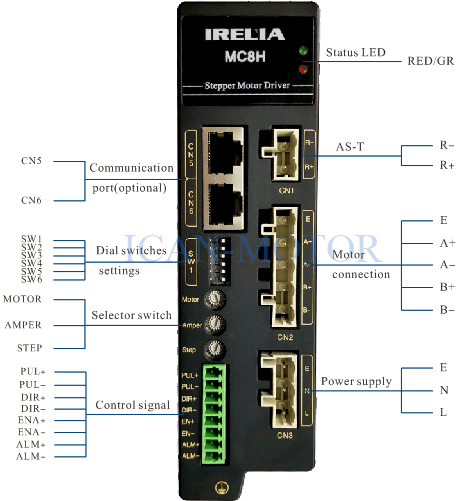
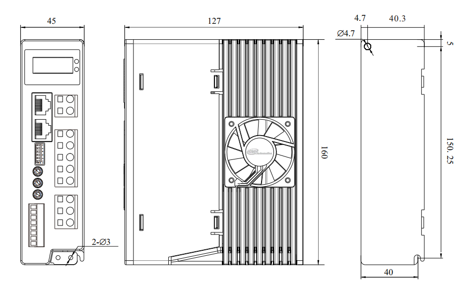
♦ High voltage nema 42 stepper motor driver
♦ Support PUL/DIR and CW/CCW modes
♦ Low noise, low vibration
♦ Microstep emulation
♦ Advanced DSP-based current control(0.5-8.0A) matches nema17-nema41
♦ Easy setup via DIP switches for micro-stepping resolution(16)
Electrical indexes
Driver parameters | Minimum value | Rated value | Maximum value | unit |
Output current | 0.5 | – | 8.0 | A |
Input voltage | 80 | 220 | 265 | VAC |
Input Pulse Width | 250 | 5E+8 | ns | |
Input Pulse Frequency | 1 | 1M | V | |
Input signal voltage | 3.6 | 5 | 24 | VDC |
Driver interface and wiring diagram
Power supply and motor wiring
CN1 | Function |
R- | AS-T |
R+ | |
CN3 | Function |
E | Ground terminal |
N | Powerful supply terminals (VAC80~265V) |
L |
CN2 | Function |
E | Earth terminal |
A+ | Motor phase A |
A- | |
B+ |
Motor phase B |
B- |
Item | Function |
PUL+ |
Pulse control signal: effective pulse falling edge, |
PUL- | |
DIR+ |
Direction control signal: High and low level pulse signals, |
DIR- | |
ENA+ |
Enable control signal: When effective(high level 5~24V), |
ENA- | |
ALM+ | Alarm signal output(OC). The maximum voltage is 24V, the maximum saturation current is 100MA |
ALM- |
Dial switches | Function |
SW1 | Communication setting reserved |
SW2 | |
SW3 | |
SW4 |
Self-testing |
SW5 | Single/Double pulse |
SW6 | Half/full current locking |
Phase current is set by “AMPER” knob, and the current value is shown in the table below.
Dial witches | 0 | 1 | 2 | 3 | 4 | 5 | 5 | 7 |
Running Current | 0.5A | 1A | 1.5A | 2.0A | 2.5A | 3.0A | 3.5A | 4.0A |
Dial witches | 8 | 9 | A | B | C | D | E | F |
Running Current | 4.5A | 5.0A | 5.5A | 6.0A | 6.5A | 7.0A | 7.5A | 8.0A |
Automatic idle current reduction to reduce heat after motor stops moving for 0.1 second if SW6 is set “off”.
Subdivision is set by “STEP” knob, 16 kinds of subdivision are optional.
Dial witches | 0 | 1 | 2 | 3 | 4 | 5 | 5 | 7 |
Subdivision(p/rev) | 200 | 400 | 800 | 1600 | 3200 | 6400 | 12800 | 25600 |
Dial witches | 8 | 9 | A | B | C | D | E | F |
Subdivision(p/rev) | 1000 | 2000 | 4000 | 5000 | 8000 | 10000 | 2000 | 25000 |
The setting is carried out through SW4=ON. When the self-testing is started, the motor will rotate a circle and then automatically return to the initial position. It can be confirmed whether the driver power works normally and the motor wire connection is reliable.
Note: The external pulse signal will not be accepted under self-test conditions.
The two pulse control input selection is set by SW5.
CW/CCW mode: SW5=ON
PUL/DIR mode: SW5=OFF