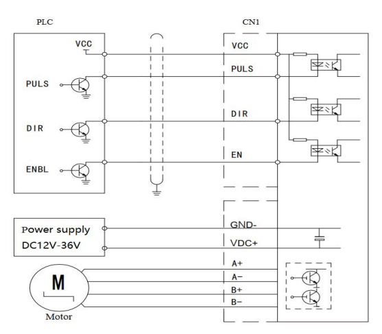
Driver interface description
| Item | Function |
| PUL | Pulse control signal: effective pulse falling edge,
pulse voltage of 5V, maximum frequency of 1MHz. |
| DIR | Direction control signal: High and low level pulse signals,
high level of 5V. |
| VCC | Common port |
| EN | Enable control signal: When effective(high level 5V),
motor is free. It is used for motor debugging. |
| GND | Power supply |
| VDC+ |
| A+ | Motor phase A |
| A- |
| B+ | Motor phase B |
| B- |
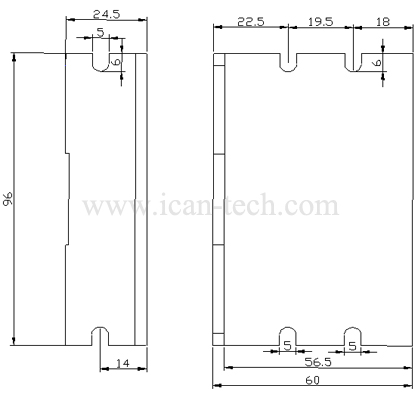
Current setting
The peak current output is set through SW1, SW2, SW3 dial switches
Half current locking
Automatic idle current reduction to reduce heat after the motor stops moving for 0.1 seconds if SW4 is set “off”.
Subdivision setting
The subdivision value is set through SW5, SW6, SW7, and SW8 dial switches, and a total of 16 subdivision settings are optional.

")