How to Solve the Inaccurate Positioning of Stepper Motors?

Stepper motors play a critical role in automation control systems, but when it works, we may encounter issues of inaccurate positioning. This phenomenon can manifest as cumulative deviations, skipped steps, or misactions. In this article, we will explore common problems causing inaccurate positioning and their solutions.

1.Losing pulses when changing direction results in accumulated deviation with more direction changes.

Stepper drivers usually have specific requirements for direction and pulse signals. Failing to meet these requirements may cause the motor to rotate in the opposite direction to the intended one. To resolve this, adjustments can be made using software to alter pulse logic or introduce delays.

2.High initial speed and acceleration may lead to step losses.

To prevent step losses, it is crucial to avoid excessively high initial speeds, especially with heavier loads. Recommended initial speeds should be kept below 1 revolution per second. Additionally, a pause should be inserted between motor’s forward and reverse rotations to avoid overshooting due to excessive reverse acceleration.

3.Software compensation in synchronous belt applications may be excessive or insufficient.

In synchronous belt applications, the belt’s elasticity can significantly impact motor motion, especially when changing directions. Proper compensation is vital to minimize positioning errors. Adjusting compensation parameters based on the actual scenario and belt characteristics is key to achieving accurate positioning.

The key to solving this problem is to adjust compensation parameters based on the actual scenario and characteristics of the synchronous belt. Applying appropriate compensation when changing direction can offset the elastic deformation of the synchronous belt and reduce positioning errors. Different application scenarios may require varying compensation values, so it is necessary to conduct experiments and tests to find the optimal parameter settings.

4.Insufficient motor power.

Increasing motor current and drive voltage (while considering suitable driver selection) or choosing a motor with higher torque can address this issue.

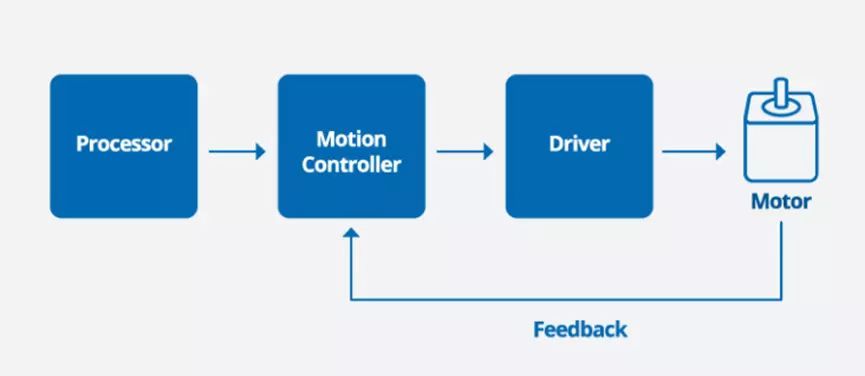
5.Controller or driver interference causing misactions.

Reducing interference from external sources and enhancing self-interference resistance are crucial. Common measures are as below:

A.Use double-braided shielded cables to separate signal lines from high-current or high-voltage wires.

B.Implement power filters to remove interference from the grid.

C.Employ optocouplers for signal transmission between devices.

In conclusion, resolving issues of inaccurate positioning in stepper motors requires precise adjustments of direction and pulse signals, setting appropriate initial speed and acceleration, compensating for synchronous belt applications, and optimizing motor power. Reducing interference and enhancing interference resistance are equally important for reliable and accurate motor positioning.


Characteristic and maintenance of brushless DC motor

Brushless DC motors are highly favored due to their compact size, lightweight design, and spark-free operation, making them ideal for use in explosive environments. In this article, we will explore the key characteristics of brushless DC motors. And give essential maintenance tips on how to keep them running smoothly.

Key Characteristics

1.Can replace DC motors, frequency conversion motors, and asynchronous motors.

2.Small size, lightweight, and high torque.

3.Excellent torque characteristics, good low-speed torque performance, large starting torque, and small starting current. Visit brushless motor sets by click here. 

4.Stepless speed regulation, wide speed regulation range, and strong overload capacity.

5.Soft start, soft stop, and good braking characteristics, eliminating the need for original mechanical or electromagnetic braking devices.

6.High efficiency, the motor itself has no excitation loss and carbon brush loss, eliminating multi-stage reduction losses, with efficiency up to 70%.

7.High reliability, good stability, strong adaptability, and simple maintenance and repair.

8.Resistant to vibration and shock, low noise, small vibration, smooth operation, and long service life.

9.No sparks, especially suitable for explosive environments, with explosion-proof types available.

10.Can choose trapezoidal wave magnetic field motor or sine wave magnetic field motor according to requirements.

Maintenance of brushless DC motor

1.Before disassembling, blow the dust on the surface of the motor .

2.Choose a clean working environment .

3.Learn the structural characteristics of the motor and the maintenance technical requirements.

4.Prepare the tools (including special tools) and equipment needed for disassembly.

5.To further understand the defects in the motor during operation, a test should be performed before disassembly . Therefore, the motor should rotate under load for detailed inspection of the temperature, sound, vibration,  voltage, current, and speed should be tested. Then perform a separate no-load test to measure the no-load current and no-load loss and record the results.

6.Cut off the power supply, remove the external wiring of the motor, and make a record.

7.Use a megohmmeter with an appropriate voltage to test the insulation resistance of the motor. In order to compare the insulation resistance values measured during the previous maintenance to judge the trend of the insulation change and insulation status of the motor, the insulation resistance values measured at different temperatures should be converted to the same temperature, generally converted to 75℃.

8.Test the absorption ratio K. When the absorption ratio is greater than 1.33, it indicates that the motor insulation has not been dampened or the degree of dampness is not severe. In order to compare with previous data, the absorption ratio measured at any temperature should also be converted to the same temperature

In conclusion, brushless DC motors offer numerous advantages over traditional DC motors and are ideal for various applications. Proper maintenance is essential to ensure that your brushless DC motor operates optimally for an extended period. If you have any concerns or questions about maintaining your brushless DC motor, please do not hesitate to contact us.

Why Brushless motor is better?

Brushless motors is becoming increasingly popular in recent years for a good reason. Compared to traditional AC motors, brushless motors have several advantages that make them a better choice for a wide range of applications. In this article, we will explore the reasons from the following aspects.

Stable speed control

Brushless motors have the ability to maintain a stable speed, even under varying loads. This is achieved through the use of feedback control systems. The system continuously monitors the motor’s speed, and adjusts the voltage and current supplied to the motor as needed to maintain the desired speed.

In contrast, AC motors typically rely on mechanical systems to regulate speed, such as changing the number of poles in the motor or adjusting the frequency of the AC power supply. These methods are less precise and can result in speed fluctuations under varying loads.

As a result, brushless DC motors are recommended for applications that require stable speed control regardless of the load fluctuation.

Higher torque at low speeds

Brushless motors have a higher torque at low speeds, which makes them well-suited for applications that require high starting torque, such as robotics, electric vehicles, and industrial machinery.


Space-saving design

Brushless DC motors have a slim body and provide high power due to the use of permanent magnets in the rotor. This compact design makes them an excellent choice for applications where space is limited. For example, brushless motors are commonly used in drones, where weight is a crucial factor in determining flight time and maneuverability.

Saving Energy

Brushless DC motors use permanent magnets in the rotor, which reduces the secondary loss of the rotor. This results in a reduction in power consumption and increased energy efficiency compared to traditional AC motors.  According to research, brushless motors can reduce power consumption by up to 35% compared to frequency conversion control of three-phase induction motors. This makes brushless motors an excellent choice for applications where energy consumption is a significant concern, such as in electric vehicles.

AC and DC Power Supply

One of the unique advantages of brushless motors is that they can use both AC and DC power supplies. In contrast, AC motors can only use AC power. This versatility makes brushless motors an excellent choice for applications where power supply options are limited .


In conclusion, brushless motors offer several advantages over traditional AC motors, including stable speed control, higher torque at low speeds, space-saving design, energy efficiency, and versatility in power supply options. These advantages make brushless motors an excellent choice for a wide range of applications, from robotics and automation to electric vehicles and aerospace engineering.

How to choose a worm gearbox?

Worm gearbox is a commonly used transmission equipment in industrial production. It is a mechanical device that uses a gear speed converter to reduce the motor speed and increase torque. Before choosing a worm gear speed reducer, we should consider the characteristics of the reducer based on the production conditions and choose the worm gear reducer accordingly.

In this article, we will introduce the worm gear reducer from several aspects such as its advantages, selection methods, and precautions, and understand how to choose the right type.

Advantages of Worm Gearbox

(1) Cost-saving: Worm gearboxes with brushless motors are cheaper than planetary reducers with brushless motors.

(2) Diversified installation methods: mainly divided into vertical and horizontal types.

The vertical installation method refers to the worm axis vertical to the ground. This installation method is suitable for situations with limited space or requiring high-power output, such as in a turbine generator.

The horizontal installation method refers to the worm axis parallel to the ground. It is usually more suitable for situations with relatively spacious spaces. This installation method can reduce the center of gravity of the reducer, thereby improving the stability and safety of the entire device. This installation method is often used in car engines.


(3) Worm gearboxes have a diversified speed ratio, and the single-stage speed ratio is 5-100. This means that the worm gearbox can reduce the speed of the input shaft to 1/5-1/100 of the original, making it more suitable for equipment that requires a lower-speed operation. .

(4) Self-locking function. The self-locking worm gear means that when the worm gearboxes stops running, it can prevent the connected mechanical equipment from rotating in the opposite direction, thereby ensuring the safety and reliability of the system.

(5) The aluminum alloy shell is light in weight, which can reduce the weight of the entire mechanical device, thereby reducing the requirements for support and improving the efficiency and performance of the device.

Selection Methods of Worm Gearbox

(1) Determine the model and size of the required reducer.

(2) Calculate the right speed ratio. The speed ratio calculation method is: speed ratio = motor speed/output shaft speed of the gearbox.

(3) Determine the torque (power) of the gearbox: the torque is crucial to the life of the gearbox. The maximum torque of the gearbox shouldn’t exceed the maximum load torque.

(4) Determine the output and input shaft directions: the gearbox has horizontal and vertical types.The output and input shaft directions are:
L direction: single input and single output, the right end is the input shaft, and the front is the output shaft.
R direction: single input and single output, the left end is the input shaft, and the forward output shaft.
V direction: single input and double output, the left end is the input shaft, and the double output shaft is positive/back
W direction: double input and single output, the input shaft is on the left and right ends, and the forward output.
F direction: double input and double output, the input shaft is on the left and right ends, and the forward/backward output.

(5) The size of the input hole and input flange.

(6) The size of the output hole or output shaft

(7)Check if other accessories are needed, such as torque arms, output flanges, single/double output shafts, etc.

Precautions for using worm gearbox:

(1) Before using the worm gear reducer, check if the form and structure of the reducer, the transmission ratio, the center distance, the output shaft structure, the input shaft connection method are correct.

(2) Check the oil level before use. This can be observed through the oil level static hole or by opening the oil plug.

(3) Gradually increase the load before use, and do not start at full load.

(4) The reducer should not be exposed to sunlight or harsh environments to avoid damage to the reducer.

(6) The standard working environment temperature of the reducer should be maintained at -5℃ to 40℃.

(7) Ensure ventilation that does not affect the motor fan’s heat dissipation.

(8) If the reducer is stored for a long time, such as more than 4 months, check if the oil seal is immersed in lubricating oil and whether the oil seal has elasticity.

To summarize, worm gearboxes are widely used in industrial production due to their cost-saving advantages, diverse installation methods, and self-locking function. Proper selection and use of worm gearboxes are crucial for their longevity and reliable performance in various applications.If you want to know more about planetary gear reducers, worm gear reducers, brushless motors,and other reduction transmission products, please contact us.

What is a servo stepper motor?

A servo stepper motor, also known as closed loop control stepper motor, is a stepper motor with feedback by adding a high-precision encoder, and controlled by servo control algorithms to achieve control of torque, speed, and position loops. It combines the advantages of stepper motor and servo motor.

Speed

After adding closed-loop control to the stepper motor, it can achieve high-speed operation, and the speed can almost be comparable to the servo motor, but it also retains the low-speed characteristics of traditional stepper motors. Servo motors can perform well at high speeds, but there may be overshoot when transitioning from high speed to low speed or stopping.

Overload capacity

The closed-loop stepper motor has higher overload output capacity (such as 1.5 times), which improves the dynamic response ability of the stepper motor.

Noise, heat, and vibration

Under non-rigorous application environments, there is almost no significant difference in noise, heat, and vibration on closed-loop stepper motors .

Precision

Due to use of feedback devices, closed loop stepper motors have ability to detect and correct for missed steps, resulting in higher precision than ordinary stepper motor ,and ensuring accurate positioning and movement.This makes them an ideal choice for applications that require precise positioning, such as in 3D printing, robotics, and automation.

Difficulty of debugging

Debugging and using closed-loop stepper motors is very simple, and only requires adjusting the position of a few potentiometers on the driver. Servo motors have hundreds of parameters, making debugging more complex, and often requiring experienced engineers.

Cost

Closed-loop stepper motors offer cost advantages over servo motors due to their lower upfront and maintenance costs, as well as simpler control systems that don’t require expensive feedback devices. This makes them a more affordable option for applications that require high precision and torque control.


Overall, closed-loop stepper motors offer high speed, precision, and overload capacity, while also being easy to use and cost-effective. They are a great choice for applications that require precise control and high performance, but do not necessarily require the high price tag of servo motors. With combination of advantages of servo and stepper motor , closed-loop stepper motors are sure to continue gaining popularity in the industry.

bldc motors

Why are BLDC motors called DC motors while they run on AC?

BLDC, also known as Electronic Commutation Motor (ECM) is a type of synchronous motor that uses a direct current (DC) power supply.
Essentially, the BLDC motor is a permanent magnet synchronous motor that converts a DC power source into a three-phase AC power source. The AC power generates electromagnetic force to drive the motor to rotate. Despite BLDC actually works on AC, why are they called DC motors? We can explain it from its history and working principle.

History of motors

The first DC motor was born in the 1840s. It was a significant milestone in the history of electrical engineering. However, the first DC motor had two main drawbacks: high capital cost and high running maintenance cost that limited its widespread use.
The cost of materials, manufacturing and specialized labor required for its construction made it an expensive technology to produce. Additionally, regular maintenance was necessary to replace the brushes and resurface the commutator, which added to the overall cost of using the motor. Because of the above, it was not affordable or practical for many potential users.

In the 1890s, the AC motor was introduced to the world, quickly gaining popularity for its simple structure, reliable performance, and low cost. This groundbreaking invention represented a significant improvement over its DC counterpart, with several advantages such as easier maintenance, fewer parts, and better insulation.
However, the AC motor also had several drawbacks. One of the significant limitations of the AC motor was its difficulty in self-starting. The low power factor was another issue, resulting in lower overall efficiency compared to DC motors. The speed regulation range was also limited, making it challenging to regulate the speed over a wide range.

So, researchers again went back to DC motor despite having a list of disadvantages. Such as brush wear, noise, and sparks during operation, which limit their application in certain fields. To solve these problems, brushless DC motors were born.
Brushless DC motors were first developed in the late 1960s. Unlike traditional brushed motors, brushless motors no longer have brushes on their rotors. This brushless design eliminates friction and sparks, and allows for more precise control of the motor’s operation. Additionally, brushless motors have higher efficiency and longer lifespan, making them an important development direction in modern motor technology.

Working principle of BLDC motors

BLDC motors consist of a stator winding and a rotating magnetic pole. The magnetic field between them follows the Lorenz theorem, which states that the interaction between current and magnetic field produces force. When the stator winding is energized, it generates a magnetic field around it, which interacts with the magnetic pole of the rotor, causing the motor to rotate. The driver periodically changes the direction of the current in the stator winding to control the stable rotation of the motor. In addition, the driver can also control the speed and position of the motor based on feedback information from sensors.

The driver converts the DC into an AC through electronic devices to control the motor’s direction and speed. The driver can use various methods to convert the DC into an AC, with one commonly used method being PWM (Pulse Width Modulation) controllers. The PWM controller produces an output signal similar to a sine wave by periodically adjusting the duty cycle of the power supply voltage, to control the motor’s rotation speed and direction.

AC or BC power input ?

Brushless motors can use both low-voltage DC and high-voltage AC. If the bldc motor controller is connected to AC, the driver converts AC to DC for the motor to work. If DC is input, the brushless motor controller does not need to convert. High-voltage AC power is easy to obtain and can provide motor power.
High-voltage AC BLDC motors are suitable for applications that require long-distance energy transport and high performance applications such as industrial robots and automated production lines. BGM company’s EH200A is a newly developed high-performance and low-cost AC brushless speed controller. It is for brushless motors with 200W and lower power. Motor speed can be regulated by the rotary knob of the controller easily. Contact us for more information!


While low voltage BLDCs are preferred for low-cost, high-reliability, and easy-to-maintain applications such as power tools and household appliances. Ultimately, the choice between the two depends on factors such as power density, efficiency, control precision, reliability, and cost.

In conclusion, the development of BLDC motors has revolutionized the motor industry by addressing the limitations of traditional DC and AC motors. With their high efficiency, longer lifespan, and precise control, BLDC motors are now widely used in various applications such as electric vehicles, drones, and industrial automation. Despite their name, BLDC motors work on AC, and their ability to use both DC and AC power input adds to their versatility. As motor technology continues to evolve, it will be exciting to see what innovations and applications the future holds for BLDC motors

Everything You Need To Know About Stepper Motors

关于步进电机你需要知道的一切 什么是步进电机? 步进电机是一种无刷同步直流电机,与许多其他标准类型的电机不同,它不仅会连续旋转多次,直到关闭传递给它的直流电压。 相反,步进电机是数字输入输出设备的精确启动和停止。它们的构造方式是,通过它的电流会撞击一系列同相排列的线圈,这些线圈可以快速打开和关闭。这允许电机进行一小部分旋转,这些单独的预定阶段,我们称之为“步骤”。 步进电机旨在将完整的旋转分成许多较小(基本上相等)的部分旋转。出于实际目的,这些可用于引导步进电机经过设定的角度或旋转。最终结果是步进电机可用于将精确运动传递到需要高精度的机械部件。 步进电机通常作为开环运动控制定位系统中的关键部件进行数字控制。它们最常用于保持或定位应用,在这些应用中,它们能够确定更明确定义的旋转位置、速度和扭矩,因此非常适合要求极其苛刻的运动控制任务。 步进电机的种类 2相步进电机 2 相步进电机是一种 2 相混合式步进电机。步进电机具有以下优点:一是过载能力好。速度不受负载大小的影响。步进电机对速度和位置有严格的要求。二是容易控制。步进电机以“步”为单位旋转,数字化特征更加明显。第三,步进电机结构简单。传统的机械速度和位置控制结构复杂且难以调整。采用步进电机后,整机结构简单紧凑。 混合式步进电机 混合式步进电机 通过半步进和微步进等技术实现更高的精度。微步进是一种增加电机内固定步数的方法,它通过编程驱动器向线圈发送交替的正弦/余弦波形。这样做通常意味着可以将步进电机设置为比标准设置更平稳、更准确。 混合式步进电机通常有两个磁极或两个齿,两个不同杯子周围的磁铁偏置在转子外部。这也意味着可以更精确地控制步进和旋转,并提供比标准步进电机更安静的运行、更高的扭矩尺寸比和更高的输出速度。 高度可靠的步进电机的强大功能 步进电机经常被误认为是伺服电机的次要,但实际上,它们的可靠性很高,就像伺服电机一样。电机与控制器输出的脉冲信号同步准确运行,实现高精度定位和速度控制。步进电机是一种 高扭矩步进电机,低速时振动小,是需要短距离快速定位的理想应用。 “步进电机?伺服电机必须有更好的性能。” 当被问及步进电机时,这是一个典型的回答。显然,人们对步进电机存在重大误解。事实上,步进电机已被用于各种类型的应用,例如先进的设备和方便的自动化仪器。 二相步进电机