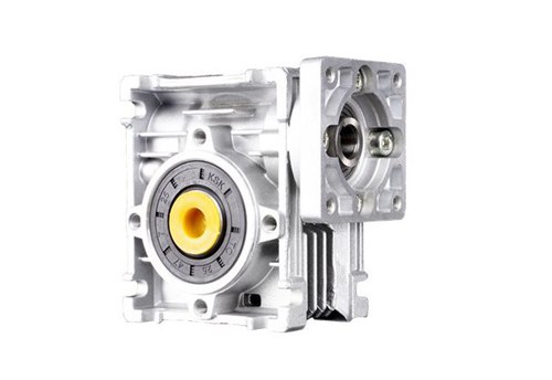
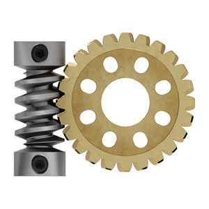
How to choose a worm gearbox?

Worm gearbox is a commonly used transmission equipment in industrial production. It is a mechanical device that uses a gear speed converter to reduce the motor speed and increase torque. Before choosing a worm gear speed reducer, we should consider the characteristics of the reducer based on the production conditions and choose the worm gear reducer accordingly.

In this article, we will introduce the worm gear reducer from several aspects such as its advantages, selection methods, and precautions, and understand how to choose the right type.

Advantages of Worm Gearbox

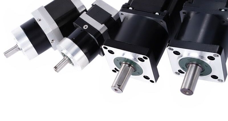
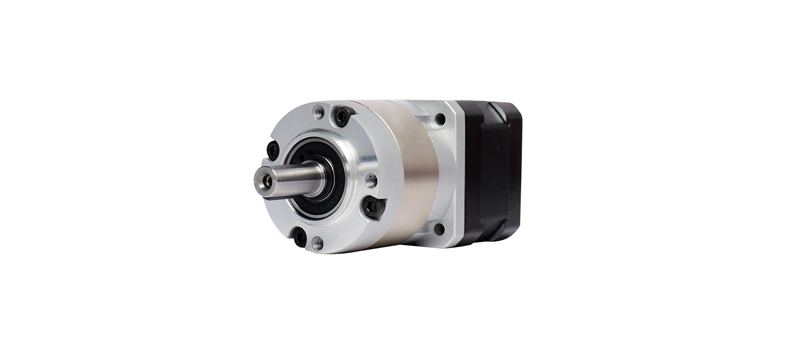
(1) Cost-saving: Worm gearboxes with brushless motors are cheaper than planetary reducers with brushless motors.

(2) Diversified installation methods: mainly divided into vertical and horizontal types.

The vertical installation method refers to the worm axis vertical to the ground. This installation method is suitable for situations with limited space or requiring high-power output, such as in a turbine generator.

The horizontal installation method refers to the worm axis parallel to the ground. It is usually more suitable for situations with relatively spacious spaces. This installation method can reduce the center of gravity of the reducer, thereby improving the stability and safety of the entire device. This installation method is often used in car engines.


(3) Worm gearboxes have a diversified speed ratio, and the single-stage speed ratio is 5-100. This means that the worm gearbox can reduce the speed of the input shaft to 1/5-1/100 of the original, making it more suitable for equipment that requires a lower-speed operation. .

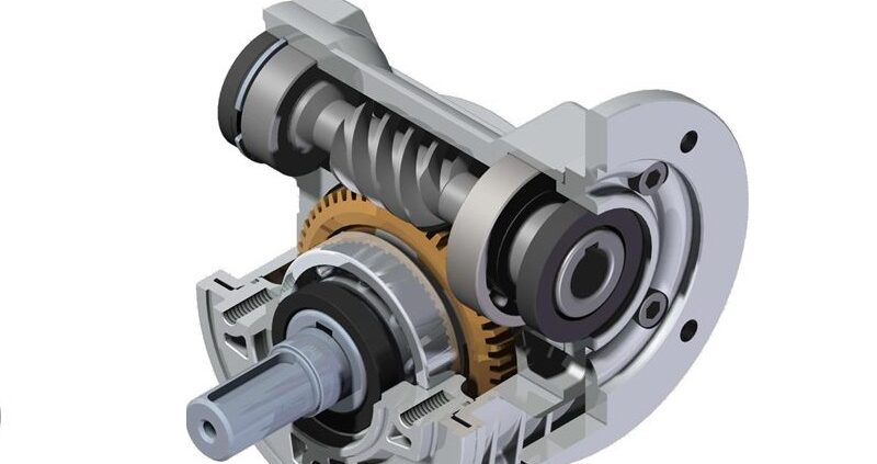
(4) Self-locking function. The self-locking worm gear means that when the worm gearboxes stops running, it can prevent the connected mechanical equipment from rotating in the opposite direction, thereby ensuring the safety and reliability of the system.

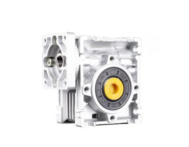
(5) The aluminum alloy shell is light in weight, which can reduce the weight of the entire mechanical device, thereby reducing the requirements for support and improving the efficiency and performance of the device.

Selection Methods of Worm Gearbox

(1) Determine the model and size of the required reducer.

(2) Calculate the right speed ratio. The speed ratio calculation method is: speed ratio = motor speed/output shaft speed of the gearbox.

(3) Determine the torque (power) of the gearbox: the torque is crucial to the life of the gearbox. The maximum torque of the gearbox shouldn’t exceed the maximum load torque.

(4) Determine the output and input shaft directions: the gearbox has horizontal and vertical types.The output and input shaft directions are:
L direction: single input and single output, the right end is the input shaft, and the front is the output shaft.
R direction: single input and single output, the left end is the input shaft, and the forward output shaft.
V direction: single input and double output, the left end is the input shaft, and the double output shaft is positive/back
W direction: double input and single output, the input shaft is on the left and right ends, and the forward output.
F direction: double input and double output, the input shaft is on the left and right ends, and the forward/backward output.

(5) The size of the input hole and input flange.

(6) The size of the output hole or output shaft

(7)Check if other accessories are needed, such as torque arms, output flanges, single/double output shafts, etc.

Precautions for using worm gearbox:

(1) Before using the worm gear reducer, check if the form and structure of the reducer, the transmission ratio, the center distance, the output shaft structure, the input shaft connection method are correct.

(2) Check the oil level before use. This can be observed through the oil level static hole or by opening the oil plug.

(3) Gradually increase the load before use, and do not start at full load.

(4) The reducer should not be exposed to sunlight or harsh environments to avoid damage to the reducer.

(6) The standard working environment temperature of the reducer should be maintained at -5℃ to 40℃.

(7) Ensure ventilation that does not affect the motor fan’s heat dissipation.

(8) If the reducer is stored for a long time, such as more than 4 months, check if the oil seal is immersed in lubricating oil and whether the oil seal has elasticity.

To summarize, worm gearboxes are widely used in industrial production due to their cost-saving advantages, diverse installation methods, and self-locking function. Proper selection and use of worm gearboxes are crucial for their longevity and reliable performance in various applications.If you want to know more about planetary gear reducers, worm gear reducers, brushless motors,and other reduction transmission products, please contact us.

What is a lead screw stepper motor?

A lead screw stepper motor, also known as a stepper motor linear actuator, is a type of motor that integrates a stepper motor and lead screw. It has the advantages of small size, easy installation, and reasonable price, and belongs to the linear motion control system.
As the trend of miniaturization, refinement of mechanical equipment becomes more popular. And the use of stepper motor series products is expanding rapidly. Lead screw stepper motors are increasingly widely used in medical instruments, testing equipment, communication, semiconductor, printing equipment, stage lighting, and other related fields.
In this article, we will classify the lead screw stepper motor from its structure and briefly introduce their characteristics.

External Drive Lead Screw Stepper Motor

In a external drive lead screw stepper motor, the lead screw and the motor rotor is combined as the motor shaft, and the nut is outside the motor, converting rotary motion into linear motion. Its lead screw is generally made of stainless steel.


Below factors should be taken into consideration during use:
1.The rated current of motors is different. The driver’s current shouldn’t exceed the rated current of the motor itself, otherwise, it will easily cause serious consequences such as overheating or burning of the motor.
2. The lead screw cannot be too long. A long lead screw may bring some risks. The biggest risk is that the actuator and lead screw will produce resonance at some positions during the motion, which will cause obvious noise. Users can buy linear actuator stepper motors with a stroke of 20-1000mm from ICAN company.

Pass-Through Shaft Lead Screw Stepper Motor

The pass-through shaft linear stepper motor integrates the nut and the motor rotor into one, with the lead screw passing through the center of the motor rotor. When the motor is energized and the rotor rotates, the motor will move linearly along the lead screw. Conversely, if the motor is fixed, the lead screw will move linearly.


When using, the following should be noted:
1. Because there is no mechanical limit between the lead screw and the nut, the lead screw will slip out if it exceeds the stroke during the operation.
2. Adding other types of lubricating oil to the lead screw is unnecessary. The lubricating oil has been added to the lead screw in the factory. Using other lubricating oils will damage the motor.

Fixed Shaft Lead Screw Stepper Motor

In some applications where it is impossible to provide anti-rotation devices for nuts or screws, this type of motor can be used. Like the pass-through shaft motor, a fixed shaft stepper linear actuator is with a nut embedded in the motor body. The lead screw is connected with the key shaft which matches with the keyway sleeve at the front end of the motor to prevent rotation, thereby realizing the linear motion of the motor.


For applications that require short strokes, such as less than 50mm, and cannot provide anti-rotation devices, it is recommended to use fixed shaft stepper linear actuator. It has advantages of compact structure and no need for anti-rotation devices. The lead screw extends from the front end but not rotate.

In conclusion, lead screw stepper motors are versatile and efficient linear motion control systems that offer several benefits . Their compact size, ease of installation, and reasonable cost make them an attractive option for a variety of applications. By considering the factors outlined in this article and selecting the appropriate lead screw stepper motor, users can ensure optimal performance and achieve their desired linear motion with ease.

pwm brushless motor control

What are basic ways of BLDC speed control?

There are various methods for speed regulation of BLDC motors, including external analog signal, external and built-in potentiometers, pulse frequency, PWM, and RS485 communication. This article will introduce various speed control methods from how it works, advantages and disadvantages, and it’s applications.

External analog signal speed regulation

BLDC motors are controlled by adjusting the voltage or current in the motor driver using external analog signals. Changing the voltage or current can alter the motor’s motion state, thus control over the motor’s speed and torque.

The driver receive commands from controller or PLC , and then outputs the corresponding voltage and current to control the motor. The controller converts external analog signals (e.g., voltage, current) into digital signals, generates control signals through calculations and logical control, and send them to the driver. While PLC achieves motor control through programming. Below chart shows the relationship between analog signal voltage and motor speed . The driver is ICAN company’s BLD-300B under closed loop no load.


As analog signal control can more accurately control the motor’s speed and torque, ensuring stability at high speed and high load, and respond quickly to different environments. This control method is typically used in applications that require higher precision and faster response speed, such as robotics, aerospace, and automotive industries.

Pulse frequency speed regulation

By adjusting the frequency of the pulse signal that drives the BLDC motor, the motor speed will be changed. This type of speed control is usually achieved through specific electronic speed controllers or inverter. These devices are installed in the motor control system and connected to the motor windings. Then set the pulse frequency through the control panel of the electronic speed controller or inverter to required speed. Once the pulse frequency is set, the motor speed can be changed by using buttons or knobs on the controller.

The advantages of BLDC pulse frequency control include high control accuracy, fast response speed, and stable speed. It can also achieve multiple operating modes, such as forward, reverse, and constant speed. Due to its efficient energy utilization and precise motor control, it has been widely used in many applications, such as wind power generation, aerospace, and other fields.

PWM speed regulation

PWM speed regulation is to modulate the constant DC voltage into a pulse voltage with constant frequency and variable pulse width. So that the average output voltage can be changed to adjust the motor speed.  Actually, it is to adjust the time duty ratio of the high level and low level of the square wave. For example, a 20% duty ratio is 20% of the high level time and 80% of the low level time.

pwm brushless motor conrol (2)

As seen from above picture, the larger the duty ratio, the larger the voltage, the higher the speed, otherwise the speed will decrease.Below shows the relationship of duty ratio and motor speed when using ICAN company ‘s BLD-300B BLDC driver under closed loop, no load.

pwm-bldc-speed-control

PWM speed regulation uses digital signals, so it has the advantages of strong anti-noise ability and longer communication distance.

External potentiometer speed regulation

The external potentiometer is a manual device that allows users to control the motor’s speed by manually rotating the potentiometer and changing the voltage signal output. Typically, the external potentiometer is installed on the front panel of the motor controller, making it easy for users to adjust the motor’s speed manually. While the adjustment range of the potentiometer is relatively limited, it offers convenient and intuitive control.

Built-in potentiometers speed regulation

Typically, BLDC motors have built-in potentiometers for speed regulation. This method does not require the use of an external potentiometer, but instead changes the motor’s speed by using a potentiometer integrated into the motor. Compared to external potentiometer speed regulation, built-in potentiometer speed regulation has higher control precision and range.

As it can provide more accurate control over the potentiometer output through the internal circuitry of the motor controller, it is suitable for applications that require more advanced control. However, for some simple applications, external potentiometer speed regulation can also provide a convenient and economical solution.

Communication signal-RS485

RS485 is a communication protocol that can be used for data communication between multiple devices. Combining RS485 with a BLDC controller can achieve BLDC speed control . Usually, there is an RS485 interface on the BLDC controller, which can be connected to master controller. Through the RS485 interface, the master controller can send commands to the BLDC controller ,and thus control the motion of the BLDC motor.

In conclusion, the choice of speed control method will depend on the specific requirements of the application, such as precision, response speed, and control range. By understanding these different methods, users can choose the most suitable way for their needs, and achieve optimal performance from their BLDC motor systems.

What is a servo stepper motor?

A servo stepper motor, also known as closed loop control stepper motor, is a stepper motor with feedback by adding a high-precision encoder, and controlled by servo control algorithms to achieve control of torque, speed, and position loops. It combines the advantages of stepper motor and servo motor.

Speed

After adding closed-loop control to the stepper motor, it can achieve high-speed operation, and the speed can almost be comparable to the servo motor, but it also retains the low-speed characteristics of traditional stepper motors. Servo motors can perform well at high speeds, but there may be overshoot when transitioning from high speed to low speed or stopping.

Overload capacity

The closed-loop stepper motor has higher overload output capacity (such as 1.5 times), which improves the dynamic response ability of the stepper motor.

Noise, heat, and vibration

Under non-rigorous application environments, there is almost no significant difference in noise, heat, and vibration on closed-loop stepper motors .

Precision

Due to use of feedback devices, closed loop stepper motors have ability to detect and correct for missed steps, resulting in higher precision than ordinary stepper motor ,and ensuring accurate positioning and movement.This makes them an ideal choice for applications that require precise positioning, such as in 3D printing, robotics, and automation.

Difficulty of debugging

Debugging and using closed-loop stepper motors is very simple, and only requires adjusting the position of a few potentiometers on the driver. Servo motors have hundreds of parameters, making debugging more complex, and often requiring experienced engineers.

Cost

Closed-loop stepper motors offer cost advantages over servo motors due to their lower upfront and maintenance costs, as well as simpler control systems that don’t require expensive feedback devices. This makes them a more affordable option for applications that require high precision and torque control.


Overall, closed-loop stepper motors offer high speed, precision, and overload capacity, while also being easy to use and cost-effective. They are a great choice for applications that require precise control and high performance, but do not necessarily require the high price tag of servo motors. With combination of advantages of servo and stepper motor , closed-loop stepper motors are sure to continue gaining popularity in the industry.

What is the difference between a servo and stepper motor?

Stepper motors are composed of a rotor, stator, permanent magnet, and driving circuit. They rotate by a fixed angle for every input signal, providing high accuracy, low noise, and rapid start and stop.
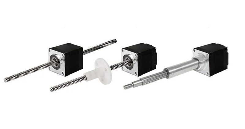
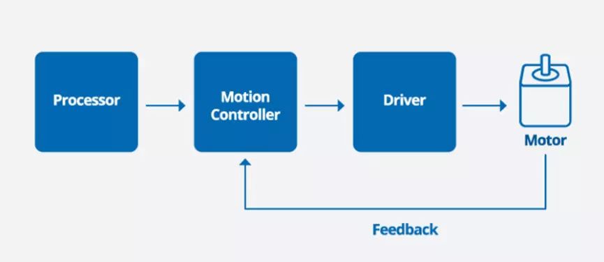
Servo motors consist of a motor body, reducer, encoder, and controller. They excel in precise position, velocity, and acceleration control. The controller can accurately adjust the motor to achieve precise motion based on set parameters.

we will compare and analyze stepper motors and servo motors from various aspects in below, including working principles, control precision, speed and overload capacity, operational performance, and cost.

Working principle

There are significant differences in the working principles between these two types of motors. A stepper motor operates using an open-loop control system, receiving electrical pulse signals to rotate and convert them into angular or linear displacement for precise control. The rotational accuracy and speed of the stepper motor are influenced by the step angle and pulse frequency.
On the other hand, a servo motor uses a closed-loop control system to achieve precise position control. The servo motor has the function of emitting pulse signals, A corresponding number of pulses are emitted for every single rotation. The controller receives and processes these pulse signals, and converts the difference between the target position into control signals for the motor.

Torque at lower speed

Stepper motors provide higher torque at low speeds than servo motors, which makes them suitable for many applications that require high torque, such as printing machines, packaging machines, and textile machines. The high torque characteristics of stepper motors also make them suitable for applications that require rapid acceleration and deceleration

Speed range

In terms of rotational speed, stepper motors have a relatively low speed, usually below 1000rpm, while servo motors can achieve higher speeds, typically above 3000rpm. So stepper motors are often used in  in low-speed applications, such as in printers, scanners, and surveillance cameras, where precise and slow movements are needed. While servo motors are often used in high-speed applications, such as in industrial automation, robotics, and aerospace systems.

Operation difficulty

Stepper motors are relatively simple to operate and control because they do not require position and speed feedback. The controller only needs to provide pulse signals to the motor to make it rotate, which makes stepper motors easy to use and maintain. In contrast, servo motors require feedback controllers to achieve high-precision and high-speed motion, which makes their control system more complex and requires more parameter adjustments and debugging. Servo motors usually require professional technicians to adjust hundreds of parameters

Control precision

Stepper motors achieve precision control by precise adjustment of the step angle, using various subdivision levels. In comparison, servo motors rely on rotary encoders to ensure control precision, which is typically higher than that of stepper motors. Stepper motors have evolved to become increasingly precise and versatile, with subdivision and encoder technologies enabling their use in 3D printing, CNC machines, and medical devices. Servo motors are the preferred choice for high-precision applications in robotics, aerospace systems, and industrial automation.

Cost

Stepper motors are generally cheaper than servo motors because of their simpler structure and lower production costs. Stepper motors do not require sensor feedback or advanced controllers to achieve high-precision motion, which makes them more cost-effective .Generally servo motor price is dozens times of stepper motor price.


In conclusion, stepper motors and servo motors have their unique advantages and disadvantages. The choice is based on applications. While with the development of technology,it has led to the emergence of a hybrid solution – closed-loop stepper motors, also known as closed-loop step motors or closed-loop stepper drives. These motors combine the precision and speed control of servo motors with the high torque and low cost of stepper motors, making them ideal for applications that require high precision, speed, and torque. The closed-loop step motor uses a feedback loop to ensure accurate position control, making it an attractive option for industries such as robotics, automation, and medical devices.

bldc motors

Why are BLDC motors called DC motors while they run on AC?

BLDC, also known as Electronic Commutation Motor (ECM) is a type of synchronous motor that uses a direct current (DC) power supply.
Essentially, the BLDC motor is a permanent magnet synchronous motor that converts a DC power source into a three-phase AC power source. The AC power generates electromagnetic force to drive the motor to rotate. Despite BLDC actually works on AC, why are they called DC motors? We can explain it from its history and working principle.

History of motors

The first DC motor was born in the 1840s. It was a significant milestone in the history of electrical engineering. However, the first DC motor had two main drawbacks: high capital cost and high running maintenance cost that limited its widespread use.
The cost of materials, manufacturing and specialized labor required for its construction made it an expensive technology to produce. Additionally, regular maintenance was necessary to replace the brushes and resurface the commutator, which added to the overall cost of using the motor. Because of the above, it was not affordable or practical for many potential users.

In the 1890s, the AC motor was introduced to the world, quickly gaining popularity for its simple structure, reliable performance, and low cost. This groundbreaking invention represented a significant improvement over its DC counterpart, with several advantages such as easier maintenance, fewer parts, and better insulation.
However, the AC motor also had several drawbacks. One of the significant limitations of the AC motor was its difficulty in self-starting. The low power factor was another issue, resulting in lower overall efficiency compared to DC motors. The speed regulation range was also limited, making it challenging to regulate the speed over a wide range.

So, researchers again went back to DC motor despite having a list of disadvantages. Such as brush wear, noise, and sparks during operation, which limit their application in certain fields. To solve these problems, brushless DC motors were born.
Brushless DC motors were first developed in the late 1960s. Unlike traditional brushed motors, brushless motors no longer have brushes on their rotors. This brushless design eliminates friction and sparks, and allows for more precise control of the motor’s operation. Additionally, brushless motors have higher efficiency and longer lifespan, making them an important development direction in modern motor technology.

Working principle of BLDC motors

BLDC motors consist of a stator winding and a rotating magnetic pole. The magnetic field between them follows the Lorenz theorem, which states that the interaction between current and magnetic field produces force. When the stator winding is energized, it generates a magnetic field around it, which interacts with the magnetic pole of the rotor, causing the motor to rotate. The driver periodically changes the direction of the current in the stator winding to control the stable rotation of the motor. In addition, the driver can also control the speed and position of the motor based on feedback information from sensors.

The driver converts the DC into an AC through electronic devices to control the motor’s direction and speed. The driver can use various methods to convert the DC into an AC, with one commonly used method being PWM (Pulse Width Modulation) controllers. The PWM controller produces an output signal similar to a sine wave by periodically adjusting the duty cycle of the power supply voltage, to control the motor’s rotation speed and direction.

AC or BC power input ?

Brushless motors can use both low-voltage DC and high-voltage AC. If the bldc motor controller is connected to AC, the driver converts AC to DC for the motor to work. If DC is input, the brushless motor controller does not need to convert. High-voltage AC power is easy to obtain and can provide motor power.
High-voltage AC BLDC motors are suitable for applications that require long-distance energy transport and high performance applications such as industrial robots and automated production lines. BGM company’s EH200A is a newly developed high-performance and low-cost AC brushless speed controller. It is for brushless motors with 200W and lower power. Motor speed can be regulated by the rotary knob of the controller easily. Contact us for more information!


While low voltage BLDCs are preferred for low-cost, high-reliability, and easy-to-maintain applications such as power tools and household appliances. Ultimately, the choice between the two depends on factors such as power density, efficiency, control precision, reliability, and cost.

In conclusion, the development of BLDC motors has revolutionized the motor industry by addressing the limitations of traditional DC and AC motors. With their high efficiency, longer lifespan, and precise control, BLDC motors are now widely used in various applications such as electric vehicles, drones, and industrial automation. Despite their name, BLDC motors work on AC, and their ability to use both DC and AC power input adds to their versatility. As motor technology continues to evolve, it will be exciting to see what innovations and applications the future holds for BLDC motors

brushless motor

What is brushless motor?

Brushless motor, is also known as brushless dc motor or BLDC motor . The construction typically consists of a rotor with permanent magnets, a stator with windings, and sometimes Hall sensors to detect the position of the rotor.

Bldc stator

The stator is usually made up of stacked steel laminations with axial slots for winding. Most BLDC motors consist of three stator windings connected in a star or “Y” formation, which is  3 phase brushless motor. This design provides a more efficient and reliable operation compared to other types of motors.

Bldc rotor

The rotor part of a BLDC motor is composed of permanent magnets, most commonly rare-earth alloy magnets such as Nd, SmCo, and NdFeB. That is why BLDC is also permanent magnet brushless dc motor.
The number of poles can vary between 2 to 8 depending on the application, with the north (N) and south (S) poles alternating. The following figure shows three different arrangements of the magnetic poles:
(a)Magnets placed on the outer periphery of the rotor.
(b)Known as an electromagnetic embedded rotor, rectangular permanent magnets are embedded in the rotor core.
(c)Magnets inserted into the rotor core.
bldc rotor

Sensored brushless motor

The BLDC motor has no brushes and requires electronic control for commutation.To make a motor rotate,the stator windings must be energized in a specific sequence, and the position of the rotor must be known to accurately energize a particular set of stator windings. To detect the rotor position ,  three Hall sensors are embedded in the stator, and convert position information into electrical signals.


When the north pole of the rotor approaches the south pole of the magnet, the Hall sensors produce a low output level. In contrast, when the north pole approaches the north pole of the magnet, the Hall sensors produce a high output level. This information is used to control the motor’s rotation and maintain the desired speed.
ICAN company offers best brushless motor with Hall sensors and can also customize sensorless bldc motor for you.

How does brushless dc motor work?

According to the Lorenz force law, a current-carrying conductor will experience a force when placed in a magnetic field. Due to the reactive force, the magnet will bear an equal and opposite force. In a brushless DC motor, the current-carrying conductor is stationary, while the permanent magnet is in motion. When the stator coil is energized, it becomes an electromagnet and produces a magnetic field.
Although the power source is DC, the switch generates a trapezoidal AC voltage waveform. Due to the interaction force between the electromagnetic stator and the permanent magnet rotor, the rotor continues to rotate. As the winding switches between high and low signals, the corresponding winding is energized as a north or south pole. The permanent magnet rotor with north and south poles aligns with the stator pole, causing the motor to rotate.

Brushless motor types

BLDC motors can be classified in various ways based on their voltage, power, performance. This diversity of classification allows for a wide range of applications for BLDC motors, making them one of the most versatile and efficient types of motors available today.
1.Classification based on voltage
Low-voltage refers to 12v brushless motor. It’s applications are power tools, toys, model airplanes, model cars, and smart homes.
Medium-voltage refers to 24v brushless motor and 48v brushless motor . It is widely used on electric bicycles, electric scooters, and electric vehicles.
High-voltage refers to 48v brushless motor and above such as 220v. It is generally applied to industrial control, power transmission, aerospace, and rail transportation.
2.Classification based on power
Small power brushless motor such as 250w bldc motor. These motors are small in size, high in efficiency, and have a long service life, and are widely used in household appliances, electric tools, toys, and other fields.
Medium power such as 500w brushless motor. These motors are widely used in machine tools, mechanical equipment, medical devices, and other fields.
Large power brushless motor with rated power between a few kilowatts and several hundred kilowatts: These motors have relatively specialized applications, such as wind power generators, ship propulsion motors, and so on.
3.Classification based on performance
High speed brushless motor
High rpm brushless motor are designed to operate at high speeds, typically 3000 rpm  and above . They are suitable for applications such as industrial automation, robotics,printing machinery and medical equipment.  Ican company’s brushless motor rpm is 1200-3000 rpm.
High torque brushless motor
These motors are designed to provide high torque at low speeds. They are suitable for applications such as conveyor system, electric vehicles,ships and lifting machinery.
Ican company offers BLDC motors of 0.66N.m to 80 N.m. Contact us to get more information now!

Diffirences of brushed and brushless motors

Brushless DC motor is a rising star in the market and is increasingly replacing brushed DC motors. Compared with brushed motors, brushless motors have more advantages:

Lightweight, thin, and high power
The rotor of the brushless motor uses permanent magnet materials, which makes it thin, lightweight, and high power. It can meet the demand for miniaturization of devices.
More energy-efficient
The rotor of the brushless motor uses permanent magnet materials, which reduces the secondary loss of the rotor and greatly reduces power consumption, helping to save energy.
Stable
Brushless DC motors are composed of a motor body and a driver. Because they operate in a self-controlled manner, they will not oscillate or lose step when the load changes suddenly.
Longer lifespan
Brushless motors can work continuously for about 20,000 hours, with a conventional lifespan of 7-10 years. Brushed motors can work continuously for about 5,000 hours, with a conventional lifespan of 2-3 years.
Maintenance and after-sales service
Brushed motors require carbon brushes to be replaced. If they are not replaced in time, they can cause damage to the motor. Brushless motors have a long lifespan, usually more than 10 times that of brushed motors, and require minimal maintenance.
Performance
Brushless motors use digital frequency control and have strong controllability. Brushed motors generally work at a constant speed after starting, and speed control is not easy. Shunt motors can also reach 20,000 RPM, but their lifespan is relatively short.
In general, the brushless motor price tends to be a lighter higher than that of brushed motor due to their more complex design and electronic commutation. However, brushless motors offer advantages such as higher efficiency and longer lifespan, which may justify the higher cost for certain applications. Ultimately, the choice between brushed and brushless motors will depend on factors such as performance requirements and budget.

What are types of gear box?


The reducer is an independent transmission device between the prime mover and the working machine, which is used to reduce the speed and increase the torque to meet the working requirements. In some cases, it is also used to increase speed and becomes a speed increaser.

According to the transmission type, the reducer can be divided into gear reducer, worm reducer, planetary reducer, and combinations of them. Reducers can be roughly subdivided into the following categories:

Worm gear reducer, planetary gear reducer, harmonic drive gear, Cycloidal pinwheel reducer, RV reducer, three-ring reducer, continuously variable transmission (CVT).

Below is the introduction of the most commonly used reducers.

1. Worm gear reducer

Worm gears are commonly used to transmit motion and power between two interleaved shafts. The worm gear and worm are equivalent to gears and racks in the intermediate plane, with the worm resembling a screw. To improve efficiency, the worm gear is usually made of non-ferrous metals (such as tin bronze), while the worm is made of harder steel (such as 45 steel or 40Cr).

Features:

Has a reverse self-locking function

Can achieve large reduction ratios

The input shaft and output shaft are not on the same axis or plane

Transmission efficiency is not high

Accuracy is not high

Application: high reduction ratios and efficient power transmission in various applications, including conveyors, packaging machines, material handling equipment, and other industrial applications that require slow and steady speed reduction.


2. Planetary gear reducer

The structure of the planetary gear reducer consists of an internal ring gear tightly connected to the gearbox housing, the center sun gear driven by external power, and a set of planetary gears equally divided and combined on a carrier tray between the two. The planetary gear set is supported by the output shaft, internal gear, and sun gear. When the power is input to drive the sun gear, the planetary gears rotate and move along the trajectory of an internal gear while revolving around the center of the gear. The rotation of the planet drives the output shaft connected to the tray to output power. The main transmission structure of the planetary reducer is planetary gear, sun gear, and inner ring gear.

Features:

Small size, lightweight, high load-carrying capacity.

Small backlash, high precision.

Smooth operation, low noise, and long service life.

Large output torque, large speed ratio, high efficiency, safe performance, and maintenance-free for life.

The maximum input power can reach 104kW.

The minimum single-stage deceleration is 3, and the maximum generally does not exceed 10. The common deceleration ratio is 3.4.5.6.8.10.

The number of stages of the reducer generally does not exceed 3, but some customized reducers with large reduction ratios have 4 stages of reduction.

The maximum rated input speed of the planetary reducer can reach 18000rpm (related to the size of the reducer itself, the larger the reducer, the smaller the rated input speed) and above.

The output torque of industrial-grade planetary reducer generally does not exceed 2000Nm, and the special super-torque planetary reducer can reach more than 10000Nm.

The working temperature is generally around -25°C to 100°C and d can be changed by changing the lubricating grease.

Most planetary reducers are installed on stepper motors, BLDC motors, and servo motors to reduce speed, increase torque, and match inertia.

Application:

High torque and precise motion control applications, including robotics, industrial automation, aerospace, medical equipment, renewable energy, and automotive.

3.Cycloidal pinwheel reduce

Cycloidal pinwheel reducer, also known as cycloidal gear reducer, is a type of power transmission device that uses the principles of cycloidal motion. Its structure includes an input shaft with an eccentric double bearing called an H mechanism, which drives two cycloidal disks to rotate in opposite directions. The pinwheels, with needle-like teeth, mesh with the cycloidal disks to produce a reduction ratio. This type of reducer is known for its high torque capacity, compact size, and low noise and vibration levels. It is commonly used in industrial machinery.


4. RV reducer

The RV reducer consists of a planetary gear reducer as the first stage and a cycloidal pinwheel reducer as the second stage. The RV reducer is a compact and high ratio transmission mechanical device. It has a self-locking function under certain conditions and is one of the most commonly used reducers with low vibration, low noise, and low energy consumption.

Features:

Wide range of transmission ratio

With high torsional stiffness, the output mechanism is a two-end supported planetary frame, which uses the rigid large disk on the left end of the planetary frame as the output. The large disk is connected to the working mechanism with bolts, and its torsional stiffness is far greater than the output mechanism of a general cycloidal pinwheel planetary reducer.

Small elastic backlash under rated torque; with a reasonable design and precise manufacturing and assembly, high precision and small clearance backlash can be achieved.

High transmission efficiency.

5. Harmonic drive reducer

A harmonic drive reducer consists of a wave generator, a flexible wheel, and a rigid wheel. It usually adopts the form a of wave generator as the active component ent, a rigid wheel as the fixed component, and a flexible wheel as the output component. The rigid wheel usually has two more teeth than the flexible wheel. Through the so-called misalignment movement, motion transmission and reduction are achieved.

Features:

Low noise and high precision

High reduction ratio: A high reduction ratio of 30-320 can be achieved with a single-stage coaxial harmonic drive.

Easy installation: Three basic components achieve a high reduction ratio, and they are all on the same axis, so the kit is easy to install.

Limited service life and poor impact resistance of flexible couplings.

Compared with rigid and metallic components, the flexibility is relatively poor, and the input speed cannot be too high.

In conclusion, reducers are essential components in industrial equipment that are used to reduce speed and increase torque. There are several types of reducers. Among them, planetary and worm reducers are recommended for their features and applications. Planetary reducers are used for high torque and precise motion control applications, including robotics, industrial automation, aerospace, medical equipment, renewable energy, and automotive. While worm reducers are used for high reduction ratios and efficient power transmission in various applications, including conveyors, packaging machines, material handling equipment, and other industrial applications that require slow and steady speed reduction.

What does gearbox do?

Gear is a mechanical component widely used in mechanical transmission. From small gears for clocks to large gears for conveying machines, it can reliably transmit power. Different speed ratios can be obtained by matching gears with different numbers of teeth. The position of the mutual relationship between the axes can be freely changed. It can be used for transmission between various axes such as parallel axes, intersecting axes, and staggered axes.

The gearbox functions as a device that transfer speed and torque between the motor and working machines. Motors usually include AC motors, BLDC motors, stepper motors, etc. Working machines include cranes, material conveyors, mixers, etc. The motors generally have high speed, while most working machines operate under heavy load and low speed.  By meshing the gear with a small number of teeth on the input shaft with a larger gear on the output shaft, the gearbox (gear reducer) reduces speed and increases torque.

What are the types of gearboxes?

There are three types of gearboxes according to the gear axis: parallel shaft, intersecting shaft, and staggered shaft.

Parallel shaft gears include spur gears, helical gears, helical racks, internal gears, etc.

The intersecting shaft gears include straight bevel gears, zero-degree bevel gears, curved bevel gears, etc.

Staggered shaft gears include staggered shaft helical gears, halberd gears, worm gearboxes, etc.


What are the Characteristics of the Gearbox?

1. Reduce the speed and increase the torque

In practical use of the motor, when considering other functions and requirements, it is difficult to only use the rated speed of the motor. So it is necessary to reduce the motor speed, and a reducer is often used. While decelerating, the reducer will increase the output torque of the motor. Commonly used geared motors are brushless planetary geared motors, brushless dc motors with gearboxes, stepping planetary geared motors, stepping motors with gearboxes, closed-loop stepping planetary geared motors, AC geared motors, etc.

2. Reduce the inertia of the motion mechanism

In the design and development of mechanical structures, It is usually necessary to consider whether the inertia of the moving equipment matches. If not, the stability of motion, accuracy, and service life of the device will be reduced. It is not advisable to increase the motor without limitation to match the motion inertia. Therefore, this problem can be solved by adopting a reducer.

3. The reducer can effectively improve the accuracy

High-precision low-speed motors are expensive. But the combination of a high-speed motor and gearbox will reduce the transmission error during the deceleration, and the price is low. For example, the common combination is a brushless DC motor with a planetary gearbox.

4. Locking mechanism

The reducer has a very important function, which is the locking function. For example, the worm gear reducer has a self-locking function. When its reduction ratio reaches a certain ratio, it can almost completely shield the reverse impact of the working machinery on the motor, and even completely stop machinery motion. Many mechanical structure design engineers think that every worm gear reducer has a locking function. But in fact, the worm gear reducer only has the self-locking function at a certain reduction ratio. This speed ratio needs to reach, 30, 40, or higher.

5. Reduce production costs

As the speed reducer has the effect of reducing the speed, the motor with low power can achieve greater torque output, which achieves the effect of saving costs.

6. Optimize the mechanical structure design

Because of the use of the reducer, we can choose a motor with a smaller power, thereby simplifying our entire product design structure, so that many functional parts can be made more refined and compact, and avoid “stupid and clumsy” looking, which is also one of the reasons why mechanical design engineers are willing to choose to use reducers.


what are the applications of gearboxes?

Gearboxes are widely used in several industries such as below.

Paper industry: To ensure the smooth running of paper industry machines, paper manufacturers use different types of gearboxes made from steel, aluminum alloys, cast iron, and steel. ICAN company’s worm gearboxes are made from aluminum alloys, which have the advantage of high stability, and good heat dissipation.

worm gearbox

ICAN worm gearbox

Steel industry: The steel industry involves highly sturdy machines. Pinion and planetary gearboxes are often used in this industry.

Sugar industry: The sugar industry is one of the biggest industries that employ a tremendous variety of gearboxes such as helical, planetary gearboxes, and others.

Cement industry: The cement industry adopts gearboxes that can carry a high torque. The two main types of gearboxes that are commonly used are bevel helical and parallel shaft gearboxes, which help in the reduction of speed and engine augmentation.

Other industries:  There are other industries in that gearboxes find their usage such as packaging machinery, conveying equipment, chemical equipment, environmental protection machinery, metallurgical mining equipment, wind power generation, road construction machinery,  escalator elevator drive, shipbuilding, light industry field, metallurgical industry, building material industry, hoisting machinery, conveyor line, assembly line, etc.


In a word, gearboxes play an important role in the power transmission systems. They are available in all sizes, types,and shapes, and can be mechanical or automatic. Gearboxes can also be customized depending on every industry’s requirements. ICAN company is a leading motor and gearbox manufacturer, which offers motors and gearboxes with the highest quality and customization service.


what is a gear motor?

A gear motor, is also called a gear motor or a geared motor , is a combination of a gear reducer and a electric motor. With using of a gear head, a gear motor reduces speed and increase torque.Gear motor can be customized to meet your Voltage, Current, Speed, Power, Torque request.

plantery gear motorApplication

Gear motors are widely used in low speed and high torque occasions. Such conveying machinery, packaging machinery, food machinery, medical equipment, printing machinery, sports equipment,  other industries.

Classification

According to the type of motor, the geared motor can be divided into stepper gear motor, BLDC gear motor and so on.

According to the gear transmission form, it can be divided into gear reducer, planetary reducer, right angle reducer, worm gear reducer.

According to the accuracy level, it is divided into precision reducer and ordinary reducer.

According to the power size, it is divided into high-power reducer and low-power reducer.

Features

1.Gearedmotors are compact in structureand small in size, with beautiful appearance and strong overload capacity.

2.The transmission ratio is finely graded. the selection of ratio range is wide, which is from 2-28800.

3.Low energy consumption, superior performance.The efficiency of the reducer is as high as 96%. It has advantage of small vibration and low noise.

4.Gear motoris highly versatile as it’s easy to use and maintain . Moreover, maintenance costis low, especially for the production line. Only a few internal transmission parts need to be spared to ensure the maintenance of the normal production of the entire line.

5.It adopts a new type of sealing device, which has good protection performance and strong adaptability to the environment. It can work continuously in harsh environments such as high temperature of 80 degrees and low temperature of -10 degrees.

6.It can be matched with ordinary lifting motors, anti-riot motors, brake motors, frequency conversion motors, DC motors, and AC motors.